
In this tutorial we’ll set up a Cloner system and use Deformers on 3D meshes. There will be in-depth explanations of lighting and post-processing effects. Almost every aspect of this setup can be controlled via hardware via ArtNet, a MIDI controller, OSC controller, or on-screen using Notch’s built-in Web GUI.
face.zip (192.6 KB)
Face.obj asset download ^^^
Step: 1
To start, create a blank project, and turn on Deferred Rendering, HDR and Antialiasing in the project settings.
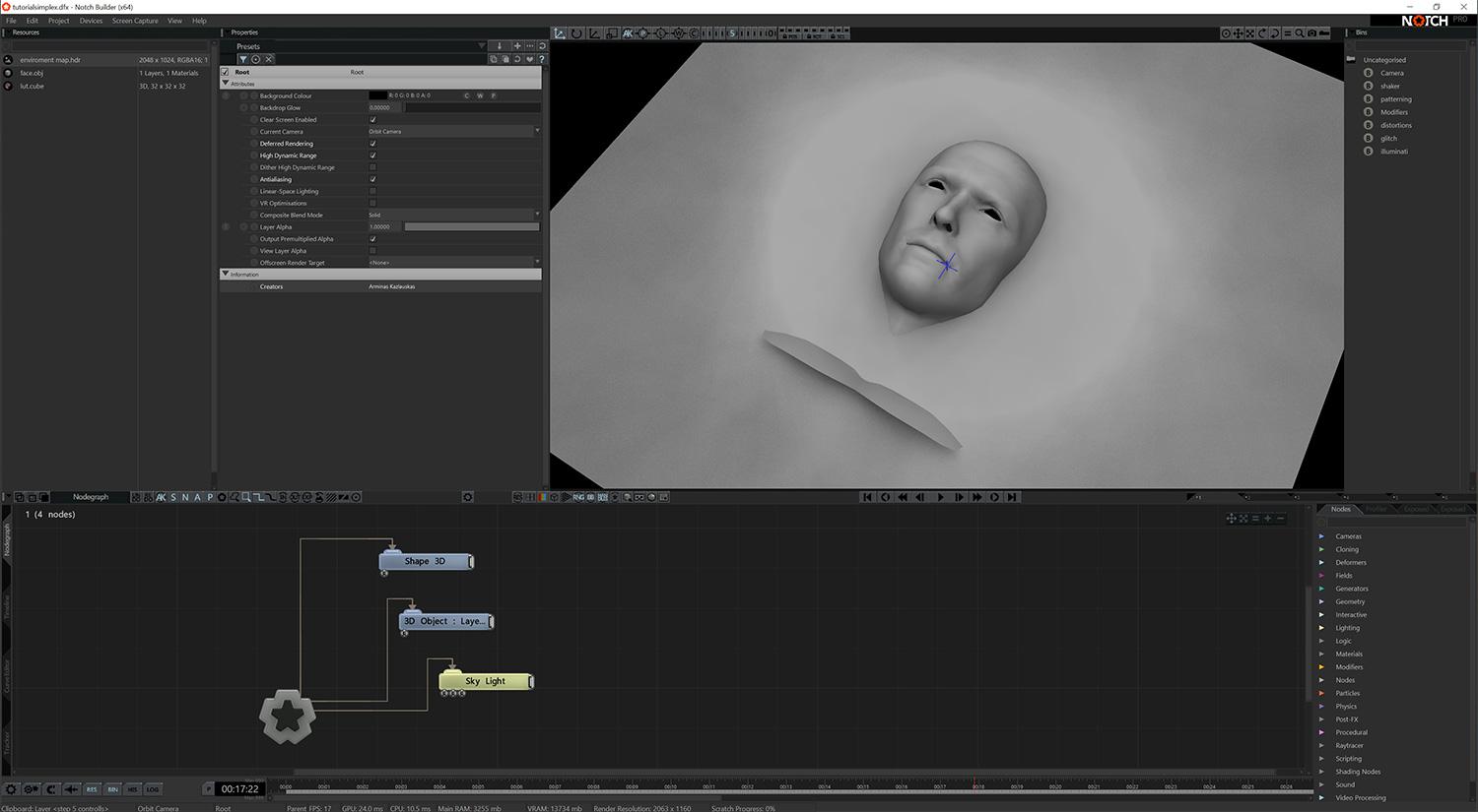
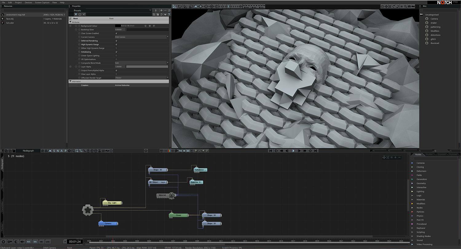
Drag and drop face.obj from your computer into the Notch application. This forms the Root node that looks like a heavily beveled star. Rotate it so that it faces upright. Transform the object by reducing size scales X, Y and Z to 0.65.
Add a ‘Sky Light’ node by selecting it from the Nodes panel in the bottom right of the interface and connect it to the ‘Root’ node. Set Num. samples to 10.
Step: 2
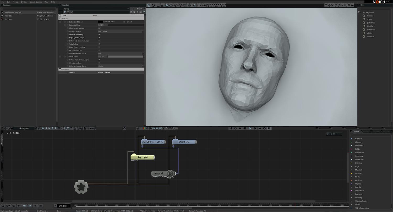
Add a ‘Shape3D’ node, and set the shape type to Plane. Set subdivisions to X: 25 and Y: 30 and place it under face.obj .
Add a ‘Material’ node and connect it to face.obj and the ‘Shape3D’ material inputs. In the material settings, enable environment mapping and reflections. Set Metallicness to 0.7, Roughness to 0.3, and Normal smoothness to 0.
In the ‘Sky Light’ node set Brightness to 5.
Step: 3
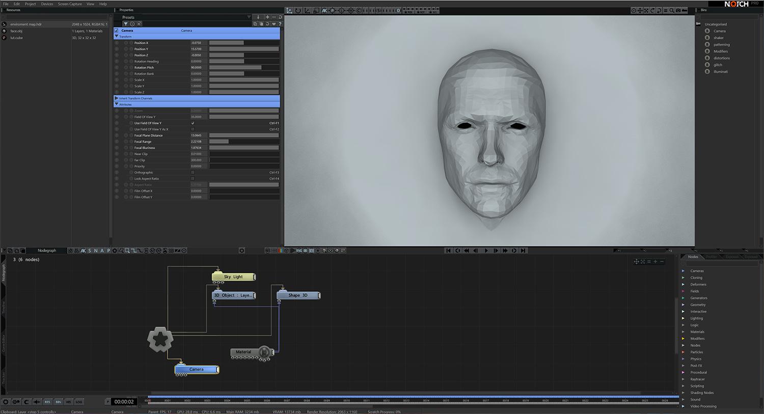
Add a ‘Camera’ node and place your camera so that face.obj is in the centre of the screen. Press 5 on your keyboard to switch the view to the camera you just added. You can switch back to the orbit camera by pressing 0 at any time.
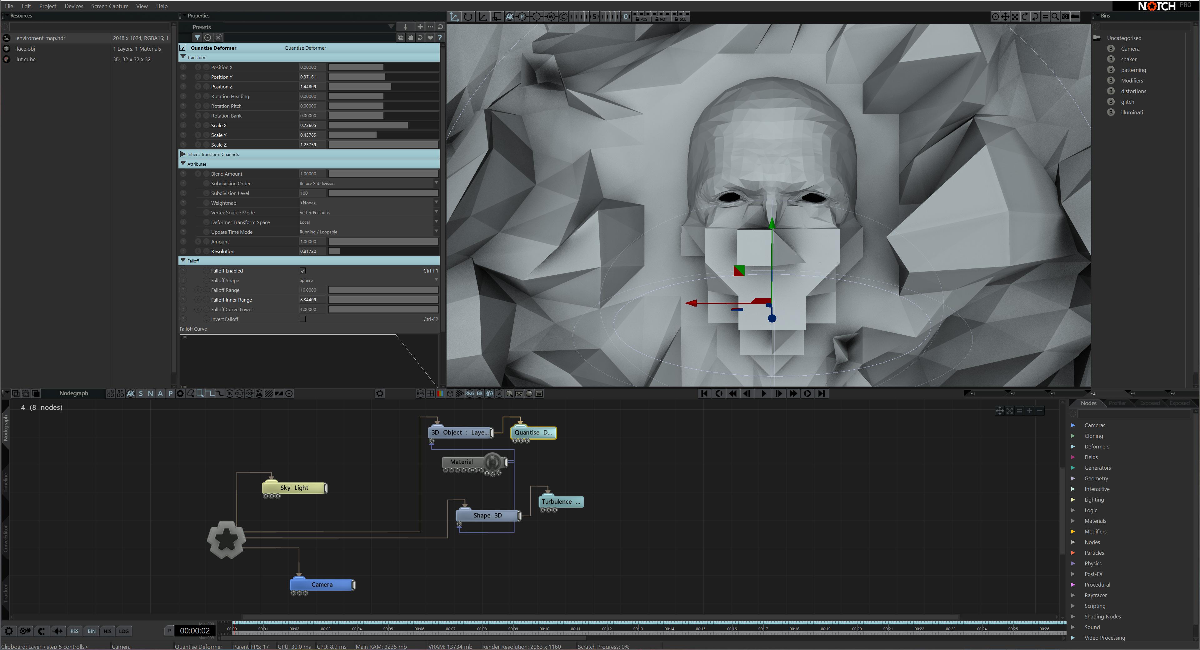
Add a ‘Turbulence Deformer’ and connect it to ‘Shape 3D’.?In the settings, turn on Falloff Enabled, and set the Range to 0 and the Inner Range to 0.14. Adjust Displacement Amount, Noise Scale, Gain, and Animation Rate to your liking.
Add a ‘Quantize Deformer’ and connect it to the face.obj node. Adjust the node placement to reveal face.obj . Turn on Falloff Enabled, set the inner range to 8 and reduce resolution to your liking.
Step: 4
Add a ‘Turbulence Deformer’ and connect it to ‘Shape 3D’.?In the settings, turn on Falloff Enabled, and set the Range to 0 and the Inner Range to 0.14. Adjust Displacement Amount, Noise Scale, Gain, and Animation Rate to your liking.
Add a ‘Quantize Deformer’ and connect it to the face.obj node. Adjust the node placement to reveal face.obj . Turn on Falloff Enabled, set the inner range to 8 and reduce resolution to your liking.
Step: 5
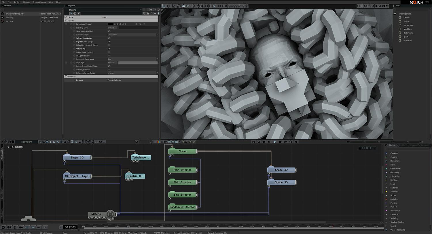
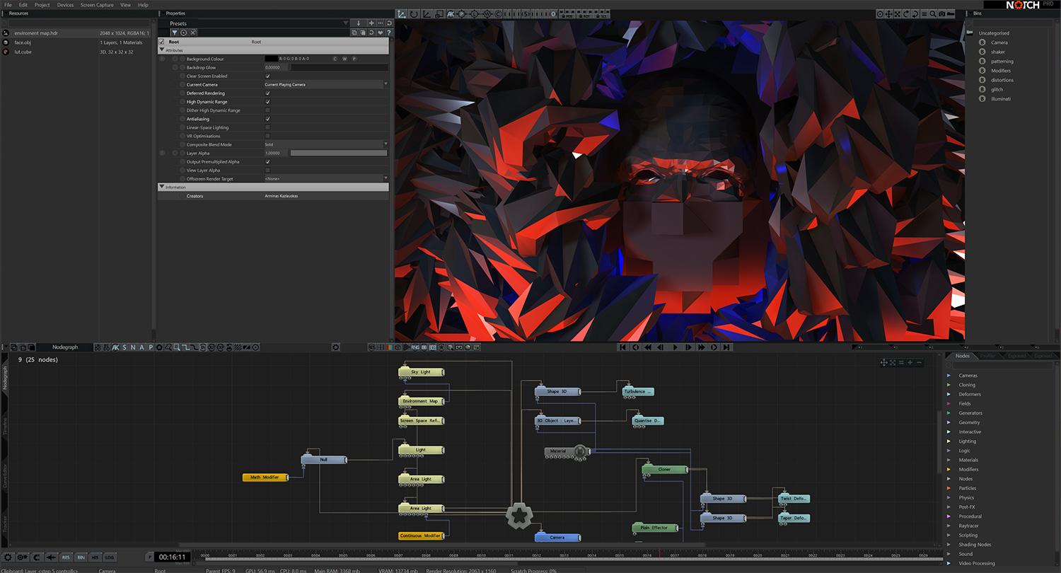
Add a ‘Cloner’ to the ‘Root’ node, set Mode to 3D Grid and Spawn mode to Iterate. Set Grid Count Size to 15 on the X, Y and Z axis.
Add a ‘Shape 3D’ node, set Shape Type to Torus, set the X and Y axis to 8.
Duplicate the ‘Shape 3D’ node, and connect both to Cloner output. Adjust the pitch angle of one ‘Shape 3D’ to 45 degrees. Input the existing material node to both ‘Shape 3D’.
Step: 6
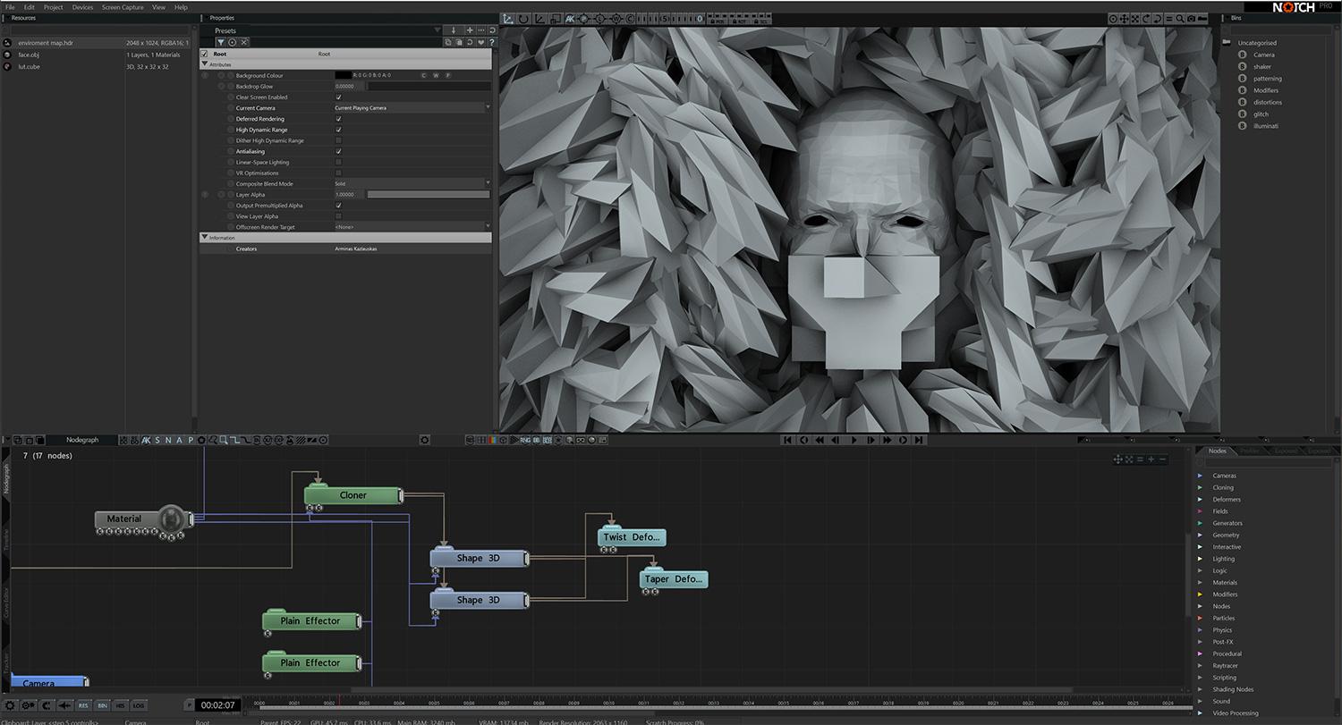
Apply the ‘Twist’ and ‘Taper’ Deformers to both ‘Shape 3D’ nodes.
Set the Displacement Amount of both Deformers to your liking. These nodes will make your Torus’s shape more abstract.
Step: 7
Here we’ll add Effectors to the effector input on the cloner to create motion.
Add a ‘Plain effector’, in Effector Transform bracket set position Y to 3.3 and pitch to 90.
Add a second ‘Plain effector’, set Scale X to 0.8 in Transform bracket. Enable Uniform Scale.
Add ‘Sine’ and ‘Randomise’ Effectors, set the Transform values to your liking.
Step: 8
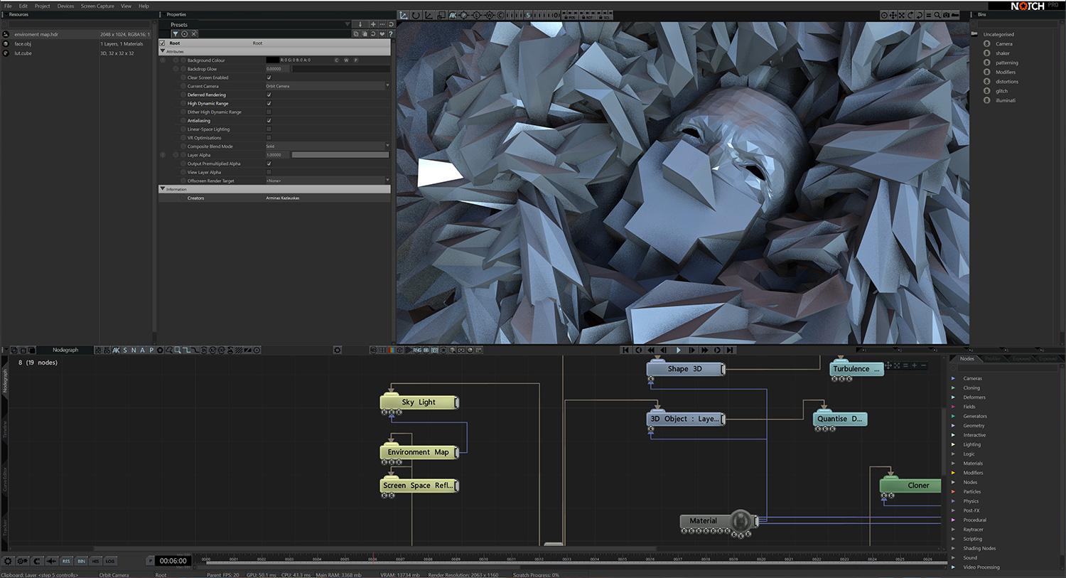
On the ‘Sky Light’ node, reduce Brightness to 0.65, and drop the Num. Sample Directions to 20.
Bellow the ‘Sky Light’, add an ‘Environment Map’ node and link it to ‘Root’. In Attributes select a .hdr picture from the Envmap Image drop-down.
Input ‘Environment Map’ to ‘Sky Light’. Below ‘Environment Map’, add a ‘Screen Space Reflections’ node.
Step: 9
Add two ‘Area Lights’ nodes. Colour one blue, and the other red. Animate their motion by adding a ‘Continuous Modifier’, attach this to the 'Area Lights’ node, where you have a choice of inputs – the little circles on the bottom left of the node – for the heading (y-axis), pitch (x-axis) or bank (z-axis).
Add a ‘Light’ node, offset it from the centre, towards the face.obj .
Add a ‘Null node and connect it to ‘Root’. Parent this ‘Null’ to the ‘Light’ – this will act as a controller for bank (ie rotation around the z-axis).
Add a ‘Math Modifier’ node and input it into the ‘Null’ rotation bank. Select Sine in Math function.
Step: 10
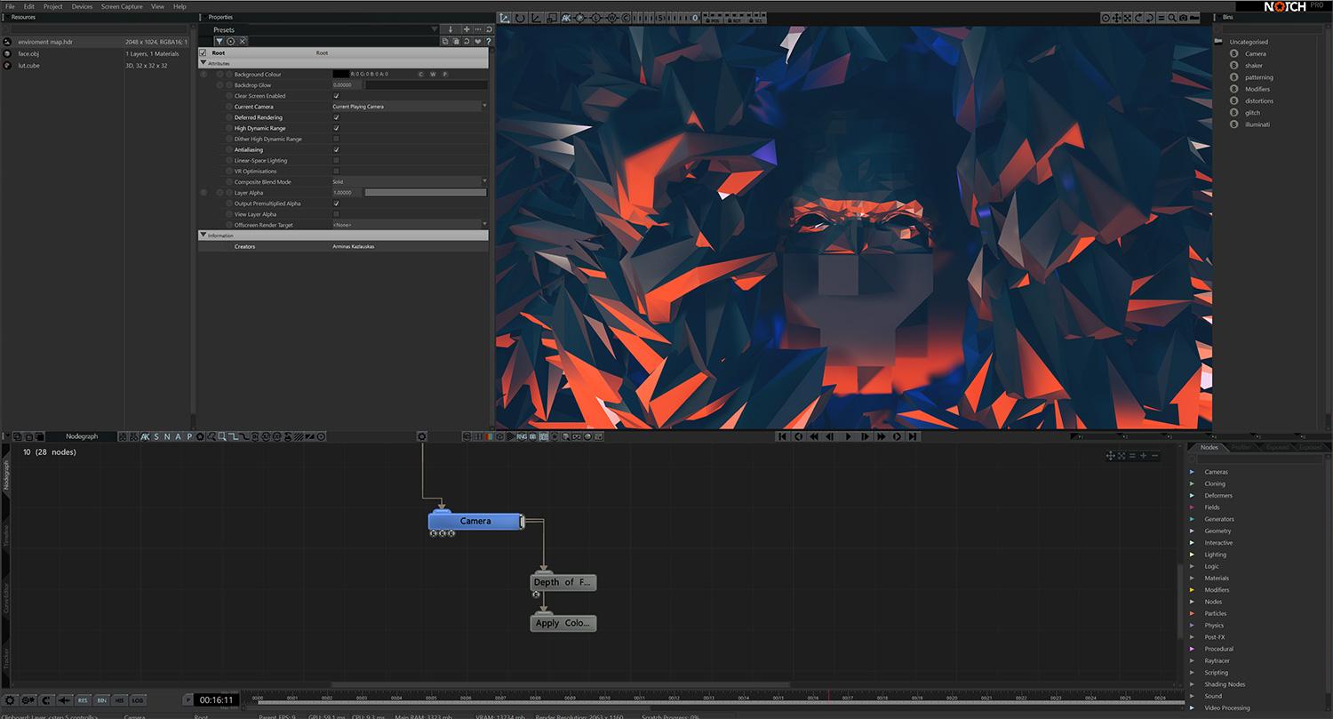
To colour grade your animation, drag a LUT from the Resources panel and connect it to the camera output. Any LUT can be applied here.
Add a’ Depth of Field’ node and attach it to the ‘Camera’s output. In the “Camera” node, enable Use Field of View Y. Adjust the Focal Plane Distance, Focal Range and Focal Blurriness to suit your preference.
Step: 11
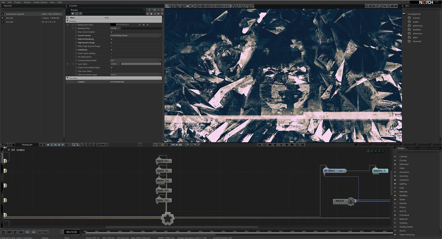
Now we’ll add post-processing effects that’s apply 2D filters over the top of our scene.
First, connect a ‘Digital Block Glitch’ to the ‘Root’ node. Below, add and connect a ‘Digital Chroma Glitch’. Below this, add and connect a ‘Motion Data Mosh’ and set its Blend Mode to Subtractive (Blend Modes work like blending modes in everything from Photoshop to Nuke).
Next, add a ‘Frame Difference’ node. Set its Blend Mode to Additive, Intensity Scale set to 2 and Num. Frames to 30.
Finally, add ‘Colour Correction’, set Saturation to 0.
Step: 12
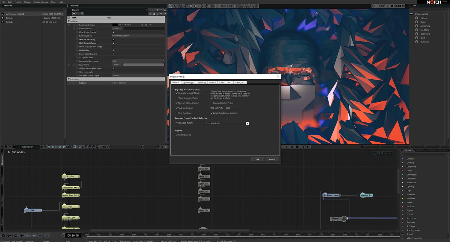
Live controls can be set in various ways, for this tutorial we will focus on Web GUI controls – so the animation can be controlled from a browser window on your computer, whether the animation itself is hosted on your computer (eg a laptop you’re taking with you to a venue) or on a server rack as part of a setup at a large concert hall or conference centre.
Select Project > Settings and a dialog will appear. In the General tab, tick Web GUI to enable it.
To the right, you will see the Web GUI Port number listed. Open your internet browser and type in localhost: followed by the number. You will now have a UI to control the Notch parameters.
Step: 13
Now lets build some controls that you can use to control the animation live in your browser…
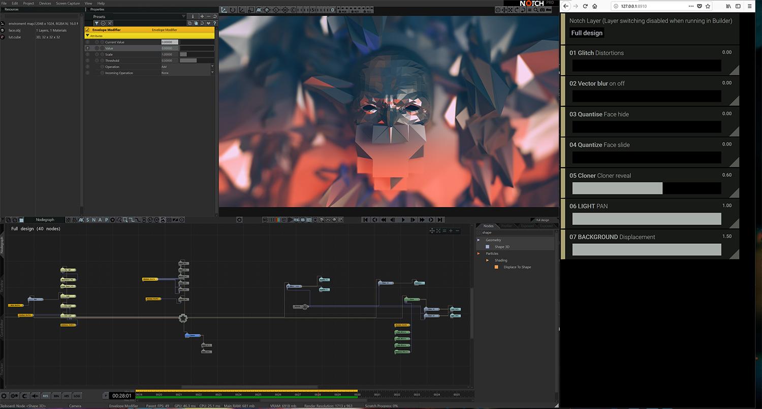
Add an “Envelope Modifier” to your Nodegraph. Connect this to the Active Inputs of all your post effects. In the Attributes of each post effect set Active to 0.
Go to the Attributes of “Envelope Modifier”, to the left of Value click on the ?, this will open a panel with exposed parameter settings.
Tick the box Set Value Min/Max. In Min. Value type in 0, and in Max. Value, 1. Next tick Expose Property and hit OK
Step: 14
Back in your web browser, hit refresh. The slider you just enabled will be available for you to use.
This process can be duplicated for “Quantize Deformer” and “Cloner”, among many other nodes. Explore the exposable settings within the nodes by clicking ? .
All of your preffered settings can be exposed and at your fingertips in real time using Notch. Happy Notching.